
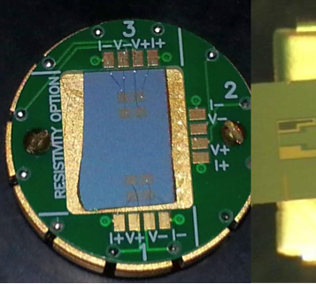
Core Advantages of Synthetic Diamond Heat Spreaders The core advantage of synthetic diamond as a heat spreading material lies in its extremely high thermal conductivity, making it an ideal functional material to solve the heat dissipation problems of high-power devices such as computer central processing units (CPUs) and light-emitting diodes (LEDs).Thermal conductivity surpassing traditional materials: It is often stated that the thermal conductivity of diamond is five times that of copper. Depending on the specific type, the thermal conductivity of Type I diamond is about twice that of copper, while Type II diamond is four to six times that of copper.Extreme thermal conductivity data: At a temperature of 273K, the thermal conductivity of Type IIa diamond can reach 2000–2200 W/(m·K), and that of isotopically pure diamond is as high as 3500 W/(m·K).Current Application Feasibility and Challenges Despite having tremendous theoretical advantages, the practical application of synthetic diamond as a heat spreading material currently faces some challenges, mainly reflected in two existing technological routes:1、CVD (Chemical Vapor Deposition) diamond films: This material has been partially trialed, but the cost is excessively high (about $10 per square centimeter, plus expensive processing fees). More importantly, its own thermal conductivity is not very ideal; measured results are similar to those of Type I diamond produced by the static pressure method, which limits its widespread application.2、Static pressure polycrystalline diamond sintered bodies: This route attempts to use low-cost static pressure single-crystal diamond (only a few cents per carat) as the raw material. However, the current process mainly produces Type Ib diamond, which has many internal structural defects and metallic inclusions, resulting in poor primary thermal conductivity. Furthermore, impurities and defects during the sintering process will further degrade thermal conductivity, and the final product's thermal performance may only be comparable to copper. It also faces the problem of high sintering and post-processing costs.Ideal Solutions and Future Feasibility As long as the correct technological route is adopted, it is entirely feasible to manufacture cost-effective heat spreading materials using synthetic diamonds. To achieve this goal, breakthroughs are needed in the following areas:Leveraging the advantages of artificial manufacturing: With synthetic diamonds, it is possible to artificially control the chemical environment of crystal growth (such as controlling the composition entering the crystal) as well as the temperature and pressure conditions to ensure the growth rate and quality of the diamond crystals.Overcoming high-quality Type IIa single-crystal raw materials: Type IIa diamond possesses excellent thermal conductivity, which is essentially due to its relatively complete crystal structure and low nitrogen content. Under current technological conditions, it is entirely possible to grow this kind of high-quality single-crystal diamond.Optimizing advanced sintering processes: Once the issue of high-quality single-crystal raw materials is solved, advanced sintering processes should be adopted to minimize defects that hinder heat propagation, such as grain boundary impurities, pores, and additives inside the polycrystalline sintered body.In summary, as long as there is an awareness of independent innovation and practical solutions are found for the three major problems of single-crystal raw material quality, thermal conductivity loss caused by the sintering process, and overall cost control, synthetic diamond heat spreading materials are not only technically feasible but also possess immense application potential.
read more+
The fundamental reason why non-magnetic diamonds have higher strength than magnetic ones lies in the destruction of crystal growth and structure by magnetic impurities (inclusions).Pure diamond crystals inherently lack magnetism. The reason synthetic diamonds exhibit magnetism is primarily because, during the high-temperature and high-pressure synthesis process, residual ferromagnetic and paramagnetic substances from the catalyst (such as Fe, Co, Ni) form inclusions within the crystal. These residual impurities directly affect the crystallization quality of the diamond, which is specifically manifested as follows:Non-magnetic diamonds have higher crystallization quality: Microscopic observation reveals that non-magnetic diamonds, which are free from the interference of magnetic impurities, exhibit full crystal growth, very smooth crystal faces, and a higher proportion of complete crystal shapes. At the same time, they contain very few internal black spots and inclusions, and have good transparency. This intact and dense physical structure allows them to withstand larger breaking loads.Magnetic diamonds have numerous structural defects: Diamonds with magnetic impurities often have incomplete crystal growth and more surface defects. In addition, the crystals contain more black spots and inclusions, resulting in poor transparency. These surface etching pits, cracks, and internal impurities easily become weak points for stress concentration when subjected to force, thereby seriously damaging the compressive strength of the diamond.In short, the increase in internal inclusions and surface crystal defects caused by magnetic impurities is the core reason why magnetic diamonds become brittle and weak. In contrast, non-magnetic diamonds, with their more perfect smooth crystal faces and higher internal purity, exhibit a measured strength that is about twice as high.
read more+
Even if diamonds have the exact same strength and particle size, differences in their thermal stability will still exist, which is primarily caused by the different content of impurities (inclusions) within the diamond crystals.Impurity content determines the initial weight-loss temperature: Experiments show that for multiple diamond single crystal samples with the same fracture load (strength) and particle size, their initial weight-loss temperatures vary significantly. This difference directly corresponds to the impurity content within the crystals: as the inclusion content within the crystal increases, the thermal stability of the diamond decreases accordingly.Impurity content is the decisive factor for thermal stability: Whether comparing diamonds of the same strength or of different particle sizes, test results indicate that the thermal stability of a diamond depends heavily on its own impurity content. High impurity content is the main reason for poor thermal stability.Internal stress destruction mechanism: As mentioned earlier, because the thermal expansion coefficients of inclusions (bubbles, catalyst metals, etc.) and the diamond matrix are different, shear stress is generated upon heating. The more impurities wrapped within the crystal, the greater the total shear stress generated when heated. This causes the diamond to reach its yield limit at lower temperatures, leading to plastic deformation and graphitization.Therefore, even if two diamonds exhibit the same macroscopic mechanical strength at room temperature, as long as there is a difference in the quantity of impurities trapped inside them, their tolerance in high-temperature environments (thermal stability) will be different.
read more+
Multiple activation treatment refers to processes such as double or triple multiple activation performed on the test core blank containing catalyst powder. First, thermal static degassing activation is conducted on the core blank within a specific temperature range and at a vacuum degree of 10−3 mmHg, ensuring that the powder core blank does not oxidize or sinter. After the degassing activation is completed, a second step of activation treatment is carried out under the protection of inert gas.Improving appearance and crystal shape: This treatment effectively removes oxygen and other impurities from the core blank to an extremely low level, making the synthesized diamond beautiful in color and highly complete in crystal shape (mainly hexahedrons and octahedrons).Increasing the proportion of coarse grains: It can significantly increase the percentage of coarse-grained diamonds. The result of the triple multiple activation treatment is particularly outstanding: the main peak of the particle size is concentrated at 45/50 mesh (accounting for 41.98%), and the secondary peak is at 40/45 mesh, with the sum of these two values exceeding 70%.Comprehensively enhancing mechanical properties: This process can significantly improve the static pressure strength and impact toughness of the diamond. It also improves the thermal impact toughness, resulting in a much smaller decrease in the toughness index of the diamond at high temperatures.
read more+
Manufacturing High-Efficiency Drilling Tools (Drill Bits): Boron-doped diamond is commonly used to manufacture drag bits and impregnated bits. For instance, in oilfield drilling, boron-doped black polycrystalline diamond bits can efficiently drill through hard rock formations like hard limestone and gravel, and the mechanical penetration rate can be more than twice that of ordinary polycrystalline diamond bits. When drilling into rocks like dolomite marble, the drilling efficiency is significantly improved, and the cost is greatly reduced.Producing Durable Cutting Tools (Circular Saw Blades): Leveraging its high wear resistance and excellent self-sharpening properties, boron-doped diamond is made into circular saw blades widely used for cutting high-hardness and brittle materials such as high-voltage electrical porcelain (containing corundum), optical glass, granite, and marble. Compared to ordinary diamond saw blades, its cutting efficiency is greatly enhanced, its service life is extended by several times, and processing costs are significantly reduced.As High-Performance Cutting Tools: Boron-doped polycrystalline cutting tools are highly effective in machining metal and non-metal materials (such as fiberglass and powder titanium alloys). Due to its surface chemical inertness, when cutting iron-group metals like high-hardness quenched steel, it not only prevents the workpiece from burning but also completely avoids "sticking" and the formation of built-up edges, thereby significantly improving the machining quality of the workpiece and the durability of the toolManufacturing High-Efficiency Grinding Tools (Abrasives): Boron-doped diamond abrasives are particularly suitable for grinding hard, tough, and difficult-to-machine materials. When grinding hard alloys, its efficiency is about 30% higher than that of ordinary diamond abrasives. For specific workpieces like fuel injector nozzles, its efficiency can even be several times that of ordinary diamond or CBN (cubic boron nitride) abrasives.Applications in the Electronics Industry (Semiconductor Materials): Because the introduction of boron atoms gives the crystal excellent hole-conducting characteristics, blue boron-doped diamond crystals are directly used as semiconductor materials in the electronics industry.
read more+
Optimizing the crystal quality of synthetic diamonds by controlling pressure and temperature mainly centers on precisely adjusting the degree of overpressure and degree of supercooling (supersaturation) during the phase transition process. These thermodynamic and kinetic conditions directly determine the nucleation rate, growth speed, and the crystal's ability to expel impurities. Specific optimization strategies are as follows:Adopt low overpressure and supercooling to grow high-quality large single crystals To obtain high-quality large single-crystal diamonds, the overpressure and supercooling must be controlled within a small range. Under these temperature and pressure conditions, although the diffusion ability of carbon atoms and their groups is relatively strong, the energy fluctuation required to generate a three-dimensional diamond crystal nucleus is very high, so the number of generated nuclei is extremely small. In an ideal state, only one crystal nucleus is generated in the system, avoiding multiple nuclei competing for carbon sources or squeezing each other, which is a necessary condition for growing high-quality large single-crystal diamonds. Furthermore, under these conditions, adopting the method of adding diamond seed crystals to promote the preferential generation and layer-by-layer spreading of two-dimensional nuclei on the seed crystal surface is an effective means to cultivate high-quality large single crystals.Adjust appropriate overpressure and supercooling to cultivate polycrystalline or abrasive-grade diamonds If the goal is to grow large-particle polycrystalline diamonds, appropriate (moderate) overpressure and supercooling need to be provided. At this time, a larger number of three-dimensional crystal nuclei are generated, and they will cross-link and combine with each other during the growth process, eventually forming polycrystals. The suitable nucleation conditions for ordinary abrasive-grade diamonds happen to lie at the junction of the single-crystal and polycrystal nucleation zones. What needs to be strictly prevented is the extreme situation where the overpressure and supercooling are too large—at this time, although the energy threshold required for nucleation is lowered, because the diffusion ability of carbon atoms and their groups becomes extremely weak, very few nuclei are generated, and it may even be difficult to successfully complete the phase transition.Strictly control the cooling rate to reduce crystal impurities Crystal purity is a key indicator of quality, which is closely related to the rate of temperature drop. If the cooling rate is too fast in the late stage of growth or during the shutdown phase, exceeding the diamond crystal's ability to expel impurities such as flux-catalysts out of its body, a large number of impurities will be trapped inside the crystal. These impurities that fail to exsolve under supersaturated conditions will severely degrade the crystal quality, making this kind of diamond extremely prone to carbonization and graphitization cracking when reheated in the metastable zone.Overall, the control of pressure, temperature, and time is essentially about influencing macroscopic/microscopic compression, shear, and thermal vibration to govern the movement, diffusion, and interaction of carbon atom groups. Only by providing stable and minimal overpressure/supercooling degrees, coupled with a slow cooling and impurity-expelling process, can the integrity of the crystal lattice structure be optimized to the greatest extent, thereby obtaining high-quality synthetic diamonds.
read more+
Based on the characteristics of synthetic diamond crystal growth, the main growth methods can be categorized into three types: the Direct Method, the Flux-catalyst Method, and the Epitaxial Method. Here is a detailed explanation of these three methods and their main differences:1. Direct Method:Growth Mechanism: This method utilizes transient static ultra-high pressure and high temperature technology, dynamic shock wave technology, or static-dynamic mixed ultra-high pressure and high temperature technology to convert carbonaceous raw materials directly from a solid or molten liquid state into diamond. Under such extreme ultra-high pressures (e.g., above 100 kilobars), the carbon atom groups in graphite undergo compression, shear, and thermal vibration, leading to shortened interlayer spacing and stacking faults, thereby exciting the sp3 hybridization state required for diamond formation.2.Flux-catalyst Method:Growth Mechanism: This uses a much lower pressure (e.g., 50-100 kilobars) than the direct method and static high-pressure and high-temperature technology to grow diamonds through the reaction of carbonaceous raw materials with specific metals and their alloys (such as Group VIII metals, chromium, manganese, etc.). These metals and alloys play a composite role of flux and catalyst, which can lower the pressure and temperature required for the phase transition and increase the phase transition rate. The geometric and electronic structures of the metals can prompt carbon atoms to enter interstices or interdiffuse, thereby exciting the transformation of non-diamond crystalline carbon atoms into the sp3 hybridization state.3. Epitaxial Method:Growth Mechanism: This method utilizes carbon atoms and their groups precipitated during the pyrolysis (such as the pyrolysis of methane, ethane, etc.) or electrolysis of carbon-containing substances to perform epitaxial growth on diamond seed crystals or certain substances acting as substrates.Nucleation Characteristic: Also primarily non-spontaneous nucleation. This method requires a high-quality seed crystal surface and usually necessitates purification of the diamond seed crystal before and during the reaction to remove unfavorable impurities, thereby prompting carbon atoms to preferentially grow epitaxially at defects.Main Differences between the Three Methods:Thermodynamic Reaction Zones: The Direct Method and Flux-catalyst Method are achieved in the diamond stable zone; whereas the Epitaxial Method is carried out in the diamond metastable zone.Nucleation Mechanisms: The Direct Method relies mainly on spontaneous nucleation, nucleating independently under extreme pressure and temperature conditions; while the Flux-catalyst Method and Epitaxial Method rely mainly on non-spontaneous nucleation, requiring the assistance of foreign substances (such as metal catalysts or diamond seed substrates) to aid nucleation and growth.Reaction Conditions and Auxiliary Materials: The direct method requires extremely harsh ultra-high pressure (often above 100 kilobars) and high temperature, without the need to add catalysts. The flux-catalyst method significantly lowers the required pressure (e.g., drops below 100 kilobars) and temperature by adding specific metals/alloys. The epitaxial method must rely on the pyrolysis/electrolysis processes of carbon-containing substances and the guidance of the seed crystal substrate.
read more+
The specific process by which the proportional valve control mode achieves a controllable pressure relief speed mainly relies on the basic principles of electro-hydraulic proportional control. The specific implementation steps are as follows:Signal input based on preset programs: First, the system sets the required pressure relief curve through a program. The control system (such as a CNC machine tool) provides the corresponding electrical input signal (usually a voltage or current signal, such as ±10V) based on this program.Signal amplification and thrust conversion: After the electronic amplifier receives the input signal, it converts it into an appropriate drive current and sends it to the proportional electromagnet inside the proportional valve. The proportional electromagnet converts the input current into a mechanical thrust acting on the valve spool.Dynamic regulation of flow and pressure: With the precise change in the displacement of the valve spool, the proportional valve can proportionally regulate the flow and pressure within the system. During the pressure relief process, the pressure sensor on the main pipeline can also convert the real-time high-pressure signal into a current signal and feed it back to the control circuit, achieving dynamic closed-loop control of the pressure by controlling the overflow rate of the proportional relief valve.In summary, the proportional valve mode converts the set program instructions into electrical signals, continuously adjusts the electromagnet thrust and valve spool displacement proportionally, and ultimately achieves dynamic regulation of the pressure relief action and overflow rate, thereby making the full-process pressure relief speed precisely controllable.
read more+
High-pressure sintering significantly promotes the densification process of aluminum nitride (AlN) ceramics by providing an additional driving force and altering the mass transfer mechanisms. The specific influence mechanisms and manifestations are as follows:Overcoming pore hindrance and providing powerful extra driving force In atmospheric pressure sintering, pores are a huge obstacle to achieving ideal density: the gas pressure inside the pores counteracts the driving force of interfacial energy, and closed pores can only be filled by extremely slow volume diffusion. Coupled with the small self-diffusion coefficient of AlN itself, pressureless sintering is extremely difficult to densify. High-pressure sintering breaks through this bottleneck. In addition to surface energy, the high pressure applied from the outside greatly supplements the driving force for densification, significantly improving sintering efficiency.2. Promoting plastic flow and multiple mass transfer (divided into two key stages)Initial stage of sintering (Stage 1): The application of external pressure first causes plastic yielding in the contact areas of AlN particles. Under stress, various creep mechanisms lead to rapid mass transfer; meanwhile, volume diffusion and grain boundary diffusion of atoms or vacancies inevitably occur, and dislocations in the grain boundaries may also climb along the boundaries, triggering grain boundary sliding. In the initial stage of sintering without additives, densification is mainly accomplished by the solid-state diffusion mechanism.Late stage of sintering (Stage 2): As the pores gradually evolve into isolated closed pores located at the intersection of grain boundaries or inside the grains, the aforementioned mechanisms continue to function. The stress at atmospheric pressure is insufficient to cause the entire material to yield, but under high-pressure conditions, the stress level is sufficient to force the vast majority of the material to undergo yielding and plastic flow, thereby effectively filling the internal pores and completing deep densification.3. Improving the density and uniformity of the microstructure When using a cubic press (six-anvil press) for high-pressure sintering, the sample is subjected to pressure from six directions simultaneously, a state very close to isostatic pressing. This uniform pressure distribution helps to improve the uniformity of the microstructure, making the sintered AlN ceramics have fine grains, a more dense and uniform structure, and indistinct grain boundaries, with its fracture mode mainly manifesting as transgranular fracture.4. The auxiliary promotional role of impurity-derived grain boundary phases Although a sintering process without additives is adopted, a small amount of impurities inevitably exist on the surface of the original raw powder. These impurities react with AlN under high temperatures to generate a small amount of grain boundary phase substances. The generation of these trace grain boundary phases also plays a certain promotional role in the densification process under high pressure.In summary, high-pressure sintering effectively lowers the sintering temperature and shortens the sintering time of AlN ceramics through powerful external mechanical driving and inducing high-temperature plastic flow of the materialFor example, without adding any sintering additives, dense AlN ceramic bodies with a relative density of up to 99.1% can be obtained by simply holding at 4.0 GPa and 1400°C for 15 minutes.
read more+
According to the provided materials, this synthetic diamond and cemented carbide composite material (PDC) has the following significant advantages when processing non-metallic materials:Combines extremely high hardness with outstanding wear resistance: When processing non-metallic materials, the tool's wear resistance directly determines its service life. The surface layer of this composite is polycrystalline diamond, which has extremely high wear resistance. Its wear ratio can reach the order of 105, which is about 80 times that of conventional YG8 cemented carbide. This allows it to maintain long-lasting sharpness when cutting non-metallic materials, significantly extending tool life.Excellent impact toughness, resistant to edge chipping: Although traditional single diamond materials have high hardness, they are very brittle and prone to chipping during cutting. This composite uses cemented carbide as a substrate, which compensates for the high brittleness of diamond. Drop-weight impact tests show it can withstand impact energy greater than 4.5 Joules (J). Therefore, when processing non-metallic materials, it can effectively resist the impact forces generated by cutting, reducing the risk of tool damage.Performance can be customized for different materials: There is a wide variety of non-metallic materials with significant differences in physical properties. A huge advantage of this composite material is that its tool performance can be flexibly adjusted by using synthetic diamond powder of different particle sizes for sintering. For instance, if processing materials that require higher toughness, fine-grained (e.g., W20) diamond powder can be selected; if processing highly abrasive materials, coarse-grained (e.g., 120/140 mesh) powder can be used to maximize wear resistance.Good thermal stability: A large amount of friction heat is often generated during cutting processes. Tests show that after holding the composite at a high temperature of 700℃ for 10 minutes, its wear ratio only drops slightly (remaining at 5.5×10⁴∼6×10⁴), indicating excellent resistance to thermal degradation below 700℃. This ensures that the tool can still maintain stable cutting performance when it heats up during the high-speed processing of non-metallic materials.In summary, cutting tools made from this composite material perfectly integrate the wear-resistant hardness of diamond with the toughness of cemented carbide, and their performance can be customized according to the specific needs of non-metallic materials, making them highly ideal processing tools.
read more+
Extremely high reliability and environmental adaptability: IPCs are specially designed for industrial environments and can adapt to harsh production conditions such as high temperature, high humidity, dust, vibration, and strong electromagnetic interference. This effectively overcomes the problems in old relay control systems where cumbersome logic and easily malfunctioning contacts led to sluggish equipment actions or even damaged anvils.Intuitive monitoring and human-machine interaction interface: Old systems (especially PLCs) often lack an intuitive display interface, making it difficult for operators to fully grasp real-time data during the synthesis process. Combined with configuration software, IPCs can provide an all-Chinese, multimedia visual interface to intuitively display the status of various valves and motors, as well as key parameters like temperature, pressure, and displacement in real-time. It can also dynamically plot the "set curve" and "actual operation curve" for operators to compare.Strong data recording and traceability analysis capabilities: Old systems usually cannot store past synthesis data. The IPC system can record core data (such as pressure, power, six-way displacement, synthesis time, etc.) and detailed alarm information in real-time during the operation process. Through historical data records, technicians can compare process parameters with the final product quality to continuously adjust and find the optimal synthesis process parameters, which was completely impossible in previous systems.Flexible process parameter management and security confidentiality mechanism: In early systems, adjusting production plans often required re-entering parameters or even modifying the underlying programs of PLCs or single-chip microcomputers, which was cumbersome and prone to errors. The IPC system can easily store multiple process curves and introduces a multi-level authority password management mechanism. Only authorized technicians can log in to modify core process parameters. This avoids misoperation and greatly protects the company's technical secrets.High control precision and easy implementation of advanced control algorithms: The core components of old analog controllers are hardware circuits, and changing the scheme requires replacing the hardware; while the control core of an IPC is software. This enables IPCs to easily apply modern advanced control theories (such as the self-adjusting factor fuzzy control and proportional control with a dead zone introduced in this system), which not only significantly improves the control precision of pressure and temperature but also improves the performance of multi-cylinder synchronous positioning, playing a key driving role in enhancing product quality and yield.
read more+
Core advantages in precision polishing (ultra-precision polishing):Ultra-fine size and extreme stability: The particle size of nanodiamonds is an order of magnitude smaller than the best conventional abrasives currently available. This not only ensures the minimum surface roughness of the polished surface but also guarantees the colloidal stability of the polishing system.Excellent surface chemistry and adsorption characteristics: Its carbon surface is highly susceptible to chemical modifications and is compatible with any polar medium, enabling nanodiamond particles to be uniformly distributed in the carrier. Additionally, its ion exchange and adsorption activity can effectively reduce the mobility of ionic and molecular products on its surface.Reducing material loss: Using nanodiamonds can decrease the component weight of the polished surface material, thereby effectively reducing the loss of the processed materials.Structural advantages and non-toxic environmental protection: The agglomerated structure of nanodiamond agglomerates helps regulate coalescence in suspended polishing systems, and the material itself is non-toxic.Improving the machinability of difficult-to-machine materials: Polishing systems containing nanodiamonds can significantly improve the polishing quality of products, showing particular advantages in ensuring the machinability of difficult-to-process materials.Core advantages in composite plating:Excellent dispersion and strengthening effects: Solid particles in traditional composite plating films are mostly at the millimeter or micrometer scale, whereas nanodiamonds, due to their extremely fine nano-size, disperse exceptionally well in the plating solution, making their strengthening effect on the coating much more pronounced.Super strong binding and diffusion forces: The surface of nanodiamond particles is rich in chemical functional groups such as hydroxyl, carboxyl, and carbonyl groups, which provide a very strong affinity and binding force with the plated surface (substrate). Furthermore, they exhibit high diffusion capabilities in composite plating.Endowing coatings with outstanding physical properties: Nanodiamonds retain the inherent excellent properties of diamonds, including super hardness, high wear resistance, heat resistance, and corrosion resistance. They can effectively improve the bonding strength between the coating and the substrate, optimize the distribution of internal stress in the plating layer, and alter the direction of crack propagation, thereby protecting workpieces that are prone to failure due to contact fatigue or high-temperature wear.Low dosage and wide applicability to substrates: In composite plating, nanodiamonds require only a very small amount to significantly improve performance. Not only can they be used for composite plating on metal surfaces, but they can also be widely applied to coatings on non-metal surfaces such as rubber, plastics, and glass.
read more+The intersection of Jingjin Road and Wei Yi Road, Luoxin Park, Economic and Technological Development Zone, Xin'an County, Luoyang City, Henan Province, China
+86 0379-6068-6876 |